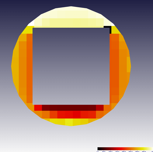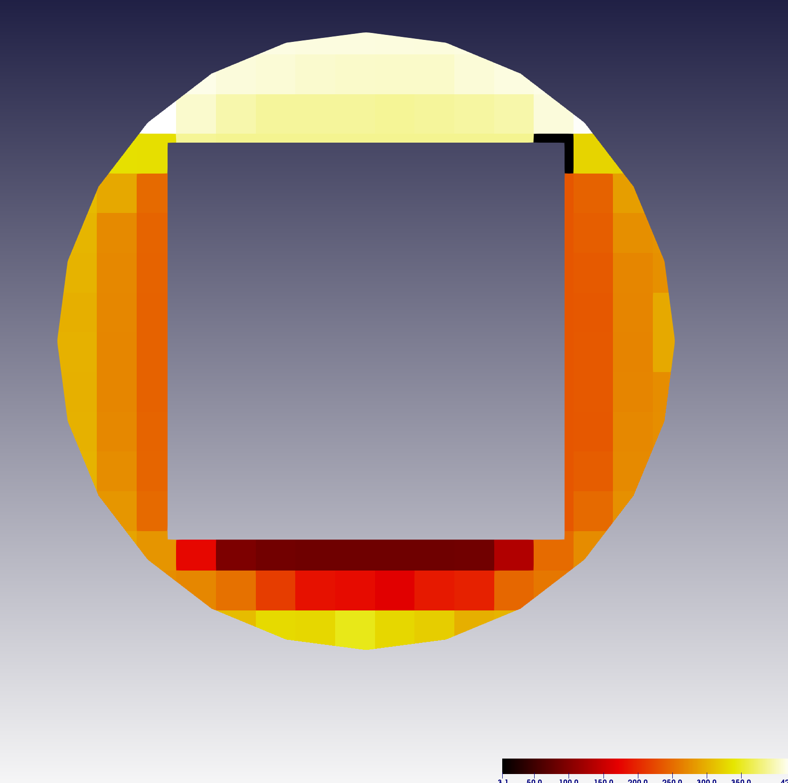

The same interpolation effect occurs for wireframe visualization too: That’s because when InterpolateScalarsBeforeMapping is off, the colors are interpolated by OpenGL using the vertex RGB values, and this can lead to the appearance of colors in your visualization which do not appear at all in the original color map.

The color is interpolated between the vertices, and the result doesn’t look anything like the color map. And it’s a good thing, because here is what the visualization looks like if we disable InterpolateScalarsBeforeMapping: That’s because ParaView has set the InterpolateScalarsBeforeMapping flag to on. But we don’t see gray, we see the red/orange/yellow progression that is defined by the color map. Or is it? If you interpolate from black to white, you should get gray in the middle. The cylinder mesh is composed of vertices at the top and bottom caps, and color is interpolated along the vertical edges. Using ParaView, I created a Cylinder source and applied the Elevation filter, then visualized it with the Radiation color map: So how does this flag affect a typical visualization? Let’s start with a simple example. If off, color mapping occurs at polygon points and colors are interpolated, which is generally less accurate.” “If on, scalars will be interpolated within polygons and color mapping will happen on a per-pixel basis. This option avoids color interpolation by using a one dimensional texture map for the colors.” Colors are interpolated after being mapped. “By default, vertex color is used to map colors to a surface. The default is off, but is it better to turn it on? The documentation says: In the API of vtkMapper, there is a flag called InterpolateScalarsBeforeMapping which can be toggled on or off. Together, these two classes provide a comprehensive API for controlling how the mesh colors are rendered. With VTK, you can define a color lookup table using the class vtkLookupTable, and you can render the mesh using a vtkMapper. Vertices with elevation close to the middle will be white. The lookup table says that vertices with the lowest elevation are blue, and vertices with the highest elevation are red. We can map scalar values to colors using a lookup table. Every vertex in the mesh has a scalar value which represents the elevation of the earth is at that location. The colors at the vertices are chosen based on the elevation. The following image shows the mesh from a different perspective, and you can see that it is composed of triangles. Helens uses color to indicate terrain elevation:

In scientific visualization, we can use colors to represent data. The image is an example of OpenGL color interpolation, and it looks kind of like a Pink Floyd laser show…
#Interpolate between two cells paraview how to#
First you are taught how to draw a triangle, then you are taught how to add vertex colors. If you do a Google image search for OpenGL triangle you’ll find a familiar image:Īn image like this can be found in almost every OpenGL tutorial, somewhere around the 2nd or 3rd lesson.

So let’s look at some examples to see how it works. The effect can be small, or quite large, depending on the data and color map that are used. The flag affects the way scalar data is visualized with colors. In VTK, there is a mapper flag called InterpolateScalarsBeforeMapping.


 0 kommentar(er)
